

How To Install Subsurface Drainage
Abstract
Subsurface drainage systems remove excess groundwater below the basis surface. Perforated plastic drain tubes are placed betwixt 1 and 2 m below the soil surface. The technique was originally called tile drainage because tile cylinders were laid end to cease in a trench. Spacing and depth of drain tubes every bit well equally lateral hydraulic conductivity of soil layers determine the rate of water removal from the field. Lateral hydraulic conductivity is by and large measured with auger hole tests. Drainage can bear on downstream water quality considering information technology changes the timing of water and chemical leaching through the soil. Drainage planning and design require all-encompassing analysis of hydrology, soil construction and texture, soil chemistry, crop rotations, field equipment, topography, waterways, and construction materials. The sizing of drainage pipes is based on the state gradient and expected menses rate to pipes. Piping layout and slope is a function of land slope and belch location in the field. If the discharge waterway is college than the drain outlet, and so a sump and pump must be installed. Gravel envelopes or fabrics protect drain tubes from sedimentation.
Keywords
- Drainage systems
- Environment
- Planning
- Network layout
- Drainage coefficient
- Envelopes
- System geometry
- Drainage structures
- Sumps
- Hydraulic conductivity
References
-
ASABE Standards (2015) Design and construction of subsurface drainage systems on agricultural lands in humid areas. ASAE EP260.5. February 2022. American Social club of Agronomical and Biological Applied science
-
Ernst LF (1955) A new formula for the adding of the permeability factor with the auger pigsty method. TNO, Groningen
-
Fogiel A, Belcher H (1991) Research literature review of water tabular array direction impacts on water quality. Agricultural Engineering Department, Michigan Country Academy/State Improvement Contractors of America, East Lansing, p 111
-
Huffman R, Fangmeier D, Elliott W, Workman Southward (2013) Soil and water conservation engineering. American Society of Agronomical and Biological Engineering, St. Joseph, Mich
-
Natural Resources Conservation Service (2001) Part 650 Engineering science field handbook affiliate 14 water direction (Drainage). http://directives.sc.egov.usda.gov/OpenNonWebContent.aspx?content=17551.wba
-
Natural Resource Conservation Service. Section xvi, National applied science handbook. chapter iv. Drainage of agricultural land. http://directives.sc.egov.usda.gov/OpenNonWebContent.aspx?content=18365.wba
-
USBR (1993) Drainage manual: a water resources technical publication. U.s. Department of the Interior, Bureau of Reclamation. pp 1–59, 147–174. http://www.usbr.gov/pmts/wquality_land/DrainMan.pdf
Author information
Affiliations
Questions
Questions
- one.
Listing the positive and negative environmental aspects of subsurface drainage.
- 2.
What measures are recommended by the NRCS to reduce the touch of drained water from farmland on the environs.
- 3.
List the features that should exist noted in a drainage reconnaissance survey.
- iv.
Based on the geometry of Fig. thirty.1 and the derivation of Eq. 30.1, are drains designed for the summit flow with the water table straight over the drain subsequently a rainstorm?
- v.
Derive a drainage coefficient equation for flow with the water table directly over the drain. Compare the ratio of menses rates based on your equation and Eq. 30.iv. Discuss why drains are non designed based on the flow rate that takes place when the h2o table is directly over the bleed.
- six.
Derive Eq. thirty.6 from Manning's equation assuming that the pipage is full and one-half total and make up one's mind whether the equation assumes that the drain is flowing one-half full of full.
Section Area A Wetted perimeter, P Hydraulic radius R Elevation width T 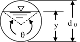
Culvert\( \frac{ane}{8}\left(\theta - \sin \theta \right){d}_0^2 \) \( \frac{1}{ii}\left(\theta \right){d}_0 \) \( \frac{1}{4}\left(ane-\frac{ \sin \theta }{\theta}\right){d}_0 \) \( \left( \sin \frac{\theta }{two}\correct){d}_0 \) - 7.
A 5 ha area has a drainage coefficient of 19.1 mm/day. The drain slope is 0.three %. Calculate the required drain size.
- 8.
Summate the required diameter of a subsurface drain for the following parameters.
Manning's n 0.017 Drain pinnacle higher up impermeable layer 3 m Drain slope s = 0.2 m/100 one thousand Hydraulic conductivity One thousand = 2 g/24-hour interval Drain spacing L = lx one thousand Length of bleed pipe Ld = 500 m Maximum WT height above drains: thou0 = 2 one thousand − 0.48 m = i m - ix.
Tin can a geotextile filter be used in a loam soil? What mesh is recommended ?
Rights and permissions
Copyright information
© 2022 Springer International Publishing Switzerland
About this chapter
Cite this chapter
Waller, P., Yitayew, Thou. (2016). Subsurface Drainage Pattern and Installation. In: Irrigation and Drainage Engineering science. Springer, Cham. https://doi.org/10.1007/978-iii-319-05699-9_30
Download citation
- .RIS
- .ENW
- .BIB
-
DOI : https://doi.org/x.1007/978-3-319-05699-9_30
-
Publisher Name: Springer, Cham
-
Impress ISBN: 978-3-319-05698-2
-
Online ISBN: 978-3-319-05699-nine
-
eBook Packages: Earth and Environmental Scientific discipline Globe and Environmental Science (R0)

Source: https://link.springer.com/chapter/10.1007/978-3-319-05699-9_30
Posted by: howardhortudy.blogspot.com
0 Response to "How To Install Subsurface Drainage"
Post a Comment